
What is being discussed here
I’m going to discuss how a program, or my Arduino program specifically, calculates register values for the Si5351a to put it on a specific frequency. I’m not going into details of how the register values are formatted into bit fields and actually sent to the chip via I2C.
Acknowledgements and sources
I’m not sure exactly which sources I borrowed pieces of code from. I took bits from libraries or programs and changed a few things. I know the method of producing quadrature output came from Hans Summers, G0UPL, and some of the basic calculation of register values did as well. A lot of what I’ve done here is to simply “reverse engineer” the code to see what it’s doing.
https://www.rfzero.net/tutorials/si5351a/ provides a nice overview of the chip and programming process.
Silicon Labs AN619 is a first resource. Some clarifications and corrections are provided by the page above and Hans Summers’ writings.
First, what is available in the component?
Below is a diagram of the Si5351a’s sections and functions
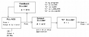
The Si5351a starts with a PLL/VCO loop. (There are two on the chip but I’m discussing one of them.) This loop adjusts the output frequency of the VCO such that it is an exact multiple of a reference crystal frequency. The program enters a divider number of the form ‘a + b/c’ to this loop and the logic divides the VCO output down to equal the crystal frequency. Put another way, you could say the crystal frequency is multiplied by ‘a + b/c’ to give the VCO output. Typical crystal frequencies are 25 MHz and 27 MHz. Mine is 25 MHz. The data sheet calls the ‘a + b/c’ divider the Feedback Multisynth Divider, because it is in the feedback loop of the PLL/VCO.
The VCO output should be in the range of 600 MHz to 900 MHz per the data sheet. It will work reliably down to 400 MHz though. This limited range dictates the first step in selecting a divider number, however.
Note that in the ‘a + b/c’ number, the value of c can be as large as 2^20 – 1 or 1,048,575. That means the VCO frequency can be set to fairly high resolution and in fact this is where we will adjust the frequency to give about 1 Hz resolution on the ham bands. The total of a + b/c can range from 15 to 90.
Following the VCO is another divider stage that divides the VCO frequency by a value of ‘d + e/f’ and can be used to take the frequency down into the low MHz range. However the chip will provide an output with lower jitter if this value is an integer and better still if it is an even integer. So we let e/f be zero and select a value for d that’s an even number. Remember that there is enough resolution in the PLL/VCO stage to provide fine tuning. This approach also simplifies the calculations required and speeds things up. The data sheet calls the ‘d + e/f’ divider the Output Multisynth Divider, because it acts on the output of the PLL/VCO.
I said the previous step allows reaching the low MHz range. If it is desired to go down into the kHz range, there is one more divider called R that can be used for this. R can be set to integer values 1, 2, 4, 8 … 128. In our example R =1 and so this stage has no effect on the output frequency.
Note that we’re down to six values to calculate which are the ‘a, b, c, d, e and f’ of the dividers ‘a + b/c’ and ‘d + e/f’. But it will actually be a lot simpler. We said that the second divider d + e/f will be an even integer, so e and f are not needed. Then in the first divider a + b/c, we will make c a constant so we are now down to three required values: a, b and d.
Method:
Our inputs are the desired output frequency Fout and reference crystal frequency Fxtal.
Recall that the second divider is to be an even integer. Known as ‘d’ above, it’s called dividerRX in my program. The output frequency of the Si5351a is the VCO frequency Fvco divided by dividerRX or
1) Fout = Fvco/dividerRX
From practical constraints, a value of 126 is a first approximation for dividerRX. To see if that value will work and keep the VCO frequency below 900 MHz, rearrange the above to give
2) Fvco = Fout * dividerRX
The program performs this multiplication and checks on whether the result is > 900 MHz. If it is not, then dividerRX will be 126. If the result is > 900 MHz, a better (smaller) value for dividerRX is determined by rearranging the equation again and using 900 MHz as the target approximate VCO frequency so
3) dividerRX = 900E6 / Fout
The remainder is truncated. Then the resulting integer is checked for odd or even. If it is odd, it is decremented by one to produce the final value for dividerRX.
Now we have a final value for dividerRX and can use equation (2) to calculate the exact value of Fvco required.
Having that value, we move to the PLL/VCO stage and calculate the required value of ‘a + b/c’. First the total value is calculated and then the individual terms are extracted to be sent to the Si5351a.
4) Fvco = Fxtal * (a + b/c), or rearrange to
5) (a + b/c) = Fvco / Fxtal
Equation (5) will give me a floating point number which is an integer plus a decimal fractional part. Truncating the number to just the integer gives me the value of ‘a’ which I call multRX.
Next I need to take the fractional part (remainder) of the result of equation (5) and use it to calculate b. Call it ‘frac’. I need a ratio b/c that equals that fractional part. I’m allowed to choose any (almost) b and c that will give the best accuracy, but for efficiency I’ll make the denominator ‘c’ be the largest value allowed, which is 2^20 – 1 or 1,048,575. This will allow the finest resolution. (More about that later.) From this I’ll calculate the value of b which in my program is called numRX.
6) numRX = frac * 1,048,575
I drop any fractional part of that result and now I have an integer which is numRX, a.k.a. ‘b’.
Now it’s just a matter of sending the three values I’ve calculated to the Si5351a. It’s never exactly that simple though, as the values must be formatted in specific ways I won’t go into here.
What about quadrature? There are registers in the Si5351a for phase offset called CLK0_PHOFF, CLK1_PHOFF and CLK02_PHOFF for the three outputs. Clocks 0 and 1 can be derived from the same PLL/VCO output so we use them. The method is to leave the clock 1 phase as-is (zero) and write the value of dividerRX to CLK0_PHOFF. This produces the 90° offset between the two.
I have a spreadsheet that will calculate the values produced by the program for any frequency, so to demonstrate the output for various desired values of Fout and a crystal frequency of 25 MHz, I have the table below.
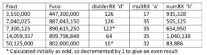
To verify or see what these numbers do, divide Fvco by dividerRX and you’ll get Fout.
Next take multRX plus numRX / 1,048,575 and mulitply that times crystal frequency 25,000,000 and you’ll get Fvco.
Note that below about 7.15 MHz the default dividerRX of 126 is used and Fvco falls out where it will. Above that frequency, smaller values of dividerRX must be used to prevent Fvco from exceeding 900 MHz.
About fixing the denominator of b/c at 2^20 – 1
Doing this simplifies things and gives the fraction a resolution of about one part per million. However, there are sometimes values of b/c using a smaller denominator that would give a greater accuracy in approximating the desired value. Consider 1/4 for example. It can be expressed as 262,144/1,048,575, but that’s not exactly one-fourth. It’s actually 0.250000238. So you can see why we say “close enough”.
There’s an algorithm for calculating the best b/c for a number with the maximum value of c specified. It’s called the Farey Algorithm. I wrote (actually, translated) a C program to do it but it was too long to include in the Si5351a VFO. That is, it takes longer to execute than my desired program speed requires. So I stay with the quick and dirty method.
Go to my Si5351a quadrature page to see my source code:
1 comments
Greetings:
You might be interested in the algorithm I used to get the a,b, and c values for the si5351, about 5 years ago.
Regards, CO7RR